How to install ods l10 mech
how to install ods l10 mech
ODS L10 mech for roller shutter
Output: 14.4 Volts 1.5Ah NiMH
Size: H 186mm
W 71mm
D 30mm
Weight: 950g
Nominal Torque: 10nm
No load speed: 16rpm
Max operating current 3.6Amps
Internal End stop limits 18 turns
Mounting the ods l10 mech
Internal or external fastening can be used to fix the ods l10 mech in position.
The ods l10 mech must be supported by the stub axle, common to standard roller shutter fittings. Ensure that the installation protects the ods l10 mech from direct exposure to water. water ingress may void the warranty.
The ods l10 mech can be used as a drill jig when useing a 3.2mm 1/8th drill bit.
NOTE Routing of the power cable need to comply with local wiring regulations.
countersink the hole, from the outside to suit the head of the fasteners. DO not over tighten these screws
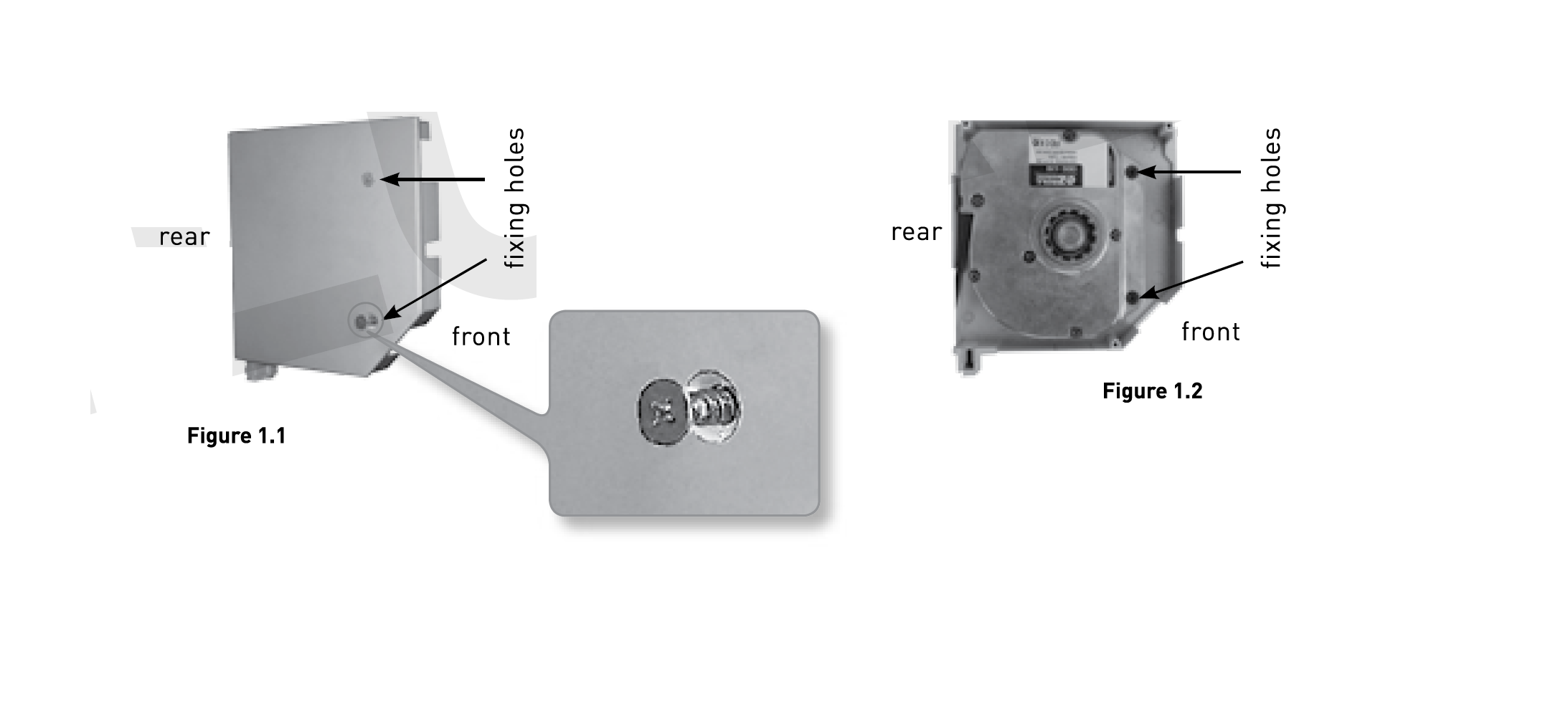
Internal fastening
For installations that use a tunnel box, window box etc.. The ods l10 mech can be attached by screwing as shown in figure 1.3. Use screws suitable for the circumstances of the installation.
Ensure that the head of the screw doesn’t protrude beyond the lid of the ods l10 mech as it will interfere with the curtain during operation.
Check out our roller shutter spare parts here
check out our other home security products here
bottom bar stopper
The OZRoll Drive system utilises the bottom bar stopper to stop the upward travel of the curtain. As this stopper needs to withstand some load, we strongly recommend that these components are closely inspected on retro-fit applications. If there is any doubt about the integrity of these existing components they should be replaced.
Setting The Internal Down Stop
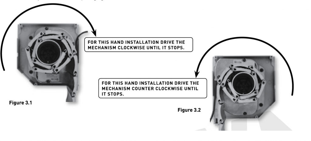
The ods l10 mech has an internal stop. This stop has to be set as the DOWN position stop. To do this , connect a controller to the ods l10 mech and drive the mech in the Down direction.
NOTE. This direction will vary depending on weather the installation is left or right handed.
Refer to figures 3.1 and 3.2. Drive the ods l10 mech until the stop engages, ie until the mech stops moving once the mech has stopped press the down button once again to ensure that the stop has been fully engaged.
how to install ods l10 mech
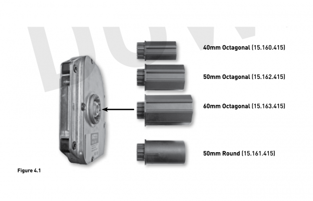
Fitting the axle
Various adaptors are available to suit different axle types. select the appropriate axle adaptor for your application.
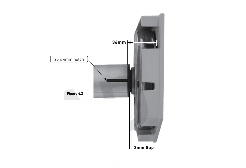
NOTE When using the 50mm round axle adaptor a 25x4mm notch will need to be cut into the axle. This is to accommodate the drive lug.
The axle must be cut to length so that there is a 36mm gap between the end of the axle and the surface the l10 mech will be mounted to. (refer to figure 4.2). This will leave a 2mm clearance gap between the axle adaptor and the output gear.
Attaching the curtain to the axle
Ensure the curtain is in the fully down position. At this stage the axle must be installed and the ods l10 mech must be set to the internal down stop position. Attach the curtain to the axle.
If using security spring hangers to connect the curtain install in such a manner as to allow the security stop to engage correctly.
If the security stop is not engaging adjust the curtin position. Do this by disengaging the axle adaptor from the olds l10 mech and rotating the axle. the axle can be indexed in increments of 30 degrees. Re-engage the axle adaptor and the ods l10 mech and check the operation of the security stop.