How to Install – Roller Shutters
Tools required
- Tape measure, Pencil, Spirit level, hammer drill, Drill bits 5mm,10mm,12mm,17mm,22mm & 25mm bits
- Masonary drill bits, 6 or 8mm depending on your screws, Screws, Hammer and a rivet gun.
you can purchase some of the tools and drill bits above from our online store to.
Instructions for a manual roller shutter installed on the wall (far one the hardest of all installs)
With your tape measure and spirit level measure out from the side of your window 53mm each side this is where your guides will sit on the wall measure out from the side of the brickwork down the bottom of the window and at the top so you can draw a line between the two and this is where the outside edge of your guide will sit ( so your line that you draw will be a vertical one).
Depending on the height of your shutter is dependent on the size of your pelmet box (the box it all rolls into at the top) it is recommended to measure the height of the actual pelmet box that has been delivered first before you measure the wall. They will come in 4 different sizes: 150mm, 165mm, 180mm & 205mm
Now measure from the top of your window up to the height of the pelmet box you have just measured it will either be 150mm,165mm, 180mm or 205mm and mark it both sides so you can see where the top of the box will sit and draw a line between the two.
Note: When drilling make sure your fixing’s are always into the brick’s and not the mortar.
Now Hold the guide up to the wall and mark on the guide the best place to drill into the brick work to secure your guides to the wall you should secure i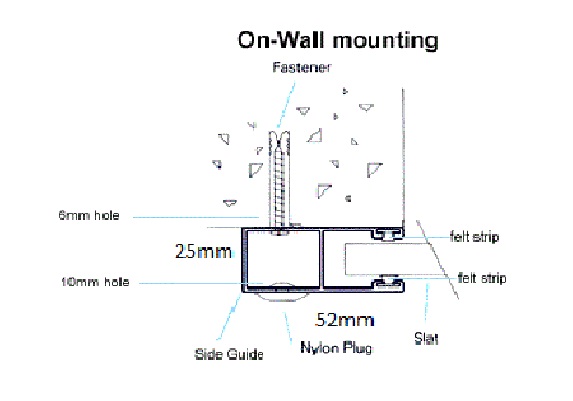 n around 3 places.
Now Drill a 6mm hole through the hollow Square section ( as per pic above) of your guide drilling from front to the back.
Note: Remember the open side of the guide is facing into the window as this what the curtain will be held in as it moves up and down your glass.
Note: its easier to lay the guides on a piece of wood so your able to drill straight through.
Drill 3 holes one at the top, middle and bottom for your screws to go into to secure it.
Now drill through the front of the guide only in the same hole to 10mm to allow for the head of the screw to pass through – now screw the guide to the wall via your holes you just drilled.
Now the pelmet legs can be slid onto the pelmet box ends (these are the silver legs supplied in the box – they slide in place at each end of the pelmet box-they connect the box to the guides-make sure they are on tight and that the green rubber lug has been taken off first).
On the side your control is going to be on measure from the top of the guide 15mm and from that point measure in 15mm, this will give you the access point for your 25mm access hole for your control.
Drill a pilot hole straight through into the house and take it slowly so not to crack your bricks while drilling be extra careful if you have tiles to the ceiling if its a bathroom or kitchen or you may crack these to.
First re drill hole with a 12mm drill bit to slowly increase the size of the hole.
Drill right the way through the brick, then redrill through with a 17mm bit
repeat this with a 22mm bit to slowly increase the diameter of the hole.
Then redrill the hole with a 25mm bit about half way in and then go inside the house to drill through the same hole but from the inside until you have drilled a hole right the way through.
Go outside and insert the white conjute from your box you were supplied with the flush fitted slotted tape guide into the hole.
You can cut this tube to fit the right depth of your cavity first pop it into the cavity draw on it with your pencil and cut to size.
this tube is so the strap/tape does not rub on your excess mortar or bricks on the inside of your wall and fray.
You can now screw and green wall plug the guides to the wall. Starting from your guide position point at the top, fix the middle and bottom of guide only at this stage so that your still able to have some guide movement at the top.
Remove the front cover of your pelmet box only and take the protective plastic cover off its stuck on. lift the back of the pelmet box into position on the wall and manoeuvre the little legs to sit into the top of the guides. Once inserted screw the top of your guides in.
In the pelmet box is a red or black round nylon spool the colour is dependant on the height of the shutter.
It has the strap/tape wound on it. Unwind all of the tape from the spool and then give it 2 to 3 winds and put a bit of strap back on the spool. secure the strap whilst unwrapping the roll of slats that are in the pelmet box slide the bottom of the shutter called a bottom bar into the top of the guide & Once in the guide you can lower the curtain into the guides until it is completely in.
Unwind all the tape off the spool again and repeat the process of 2-3 more winds to put some tape back on the spool. Thread the end of the tape back through the pelmet box into the slotted tape guide you inserted into your wall earlier ensuring there are no twists in the strap or it will be difficult to wind up if not impossible. Thread it through to the inside of the house from inside. sometimes its easier to attach the strap to a coat hanger straightened out to help you push it through the wall.
Making sure there are no twists in the strap thread through the diamond neck roller then press the diamond neck roller into the hole on the wall inside the home.
then Measure from the ground 500mm up from the floor, this is the recommended height for the winder box to be installed. Mark the position of the winder fixing points clearly on the wall by putting a screw into the screw holes and making an indentation on the wall with the screw. remove the 2 face screws of the winder box.
Remove the roller, insert strap onto the roller and insert strap through the slot in the spool inside the winder and tie a knot in the strap to secure it. Wind strap onto the spool of the winder and put the rollers and spool back into the winder box. Place the winders cover back on and the 2 face screws.
Now you can fix winder to the wall with wall plugs and screws insert your handle.
Now go back outside, if everything is working ok then insert your front cover of pelmet box on and rivett it in place and you are complete.
please feel free to send us your completed photos, so we can see what you have accomplished and publish them for others to be inspired by.
Instructions for a battery operated roller shutter (ODS) installed on the wall (easy install)
There are a number of tools and equipment required to complete the install of a battery operated shutter:
Spirit level, hammer drill & drill bits -5mm & extended 10mm, rechargeable power drill, Phillips head screwdriver bit & steel drill bits (5mm & 10mm), hammer, rivet gun, pencil, tape measure, self tapping screws, guide hole plugs, wire, a ladder and 2 lengths of timber.
Some of these tools are available from our online shop to purchase
Each standard assembled ODS – battery shutter will come with the following parts: A pelmet box with an assembled curtain and mech, a pair of guides, an E-port handset, an E port wall plate, an E series AC adaptor, rivets and guide end stops.
Plug the E-Series AC adaptor into a power point and connect it to the E-Port to charge. A red LED indicator will light up letting you know it is charging.
With your tape measure and spirit level measure out from the side of your window 53mm each side this is where your guides will sit on the wall measure out from the side of the brickwork down the bottom of the window and at the top so you can draw a line between the two and this is where the outside edge of your guide will sit ( so your line that you draw will be a vertical one).
Depending on the height of your shutter is dependent on the size of your pelmet box (the box it all rolls into at the top) it is recommended to measure the height of the actual pelmet box that has been delivered first before you measure the wall. They will come in 4 different sizes: 150mm, 165mm, 180mm & 205mm
Now measure from the top of your window up to the height of the pelmet box you have just measured it will either be 150mm,165mm, 180mm or 205mm and mark it both sides so you can see where the top of the box will sit and draw a line between the two.
Note: When drilling make sure your fixing’s are always into the brick’s and not the mortar.
Now Hold the guide up to the wall and mark on the guide the best place to drill into the brick work to secure your guides to the wall you should secure it in three places.
Now Drill a 6mm hole through the hollow Square section of your guide drilling from front to the back.
Note: Remember the open side of the guide is facing into the window as this what the curtain will be held in as it moves up and down your glass.
Note: its easier to lay the guides on a piece of wood so your able to drill straight through.
Drill 3 holes one at the top, middle and bottom for your screws to go into to secure it.
Now drill through the front of the guide only in the same hole to 10mm to allow for the head of the screw to pass through and an extra 10mm hole at the back of the guide for your ods mech wire to come out of so it can enter the wall of the home at the same point on the guide that you have drilled the wire entry hole drill the same size hole through your wall of the home so that the ods mech wire can pass down the leg of the shutter through the guide and into your wall to eh point where the eport control will be installed.
Now the pelmet legs can be slid onto the pelmet box ends (these are the silver legs supplied in the box – they slide in place at each end of the pelmet box-they connect the box to the guides-make sure they are on tight and that the green rubber lug has been taken off first).
Now look where your eport handset will be installed on the inside of the home, keeping in mind you must have the E port on the same side as the ODS mech that is inside your pelmet box.
Now drill a vertical 10mm hole in the silver box end leg for the ODS wire to run through and slide the ods motor through this hole, install the box end leg onto the pelmet ends ensuring you have removed the green lug first.
Now slide your guides onto your pelmet box slide the ODS wire down the inside SQ. section of the guide and out the 10mm pre drilled hole you drilled as an exit for it earlier. .
Once the shutter is together with guides in place get someone to help you lift the shutter onto the wall where it is to be installed, whilst some ones holding it you are then able to push the ODS cable through the hole that you have made in the wall to enable the control inside to be installed later.
Note: you can fish it out with a wire or coat hanger.
holding the shutter to the wall use your pre drilled holes on the guides to secure your roller shutter.
Insert your charge E port into the wall plate and connect the ODS wire to the terminals on the back. When you press the down button on your E-Port the curtain should begin moving down, if not then swap the wires over on the wall plate terminals.
Now remove the E-Port from the wall plate and fix the wall plate over the ODS wire ‘exit hole’ using the 3 fixing points and insert the cover plate provided. Now you can insert your E-Port back in the wall plate.
Operate the shutter a full rotation up and down multiple times to ensure it’s in working order. Once you are satisfied leave the curtain down and you have an opportunity to do any final fixing of the head box such as a tech screw into a wall or an eve.
Pop rivet the lid on the head box with the rivets provided and insert hole caps over your fixing points in the guides and your battery System installation is now complete.
instructions for an electrically operated roller shutter on the wall ( the easiest of all install’s )
All electrical work must be carried out by a qualified electrician, if you can have an issue and cannot supply a certificate of compliance we will not warranty your motor. A qualified electrician has to by law give you this form on completion. you are able to install the shutter yourself but the electrician needs to wire it up.
With your tape measure and spirit level measure out from the side of your window 53mm each side this is where your guides will sit on the wall measure out from the side of the brickwork down the bottom of the window and at the top so you can draw a line between the two and this is where the outside edge of your guide will sit ( so your line that you draw will be a vertical one).
Depending on the height of your shutter is dependent on the size of your pelmet box (the box it all rolls into at the top) it is recommended to measure the height of the actual pelmet box that has been delivered first before you measure the wall. They will come in 4 different sizes: 150mm, 165mm, 180mm & 205mm
Now measure from the top of your window up to the height of the pelmet box you have just measured it will either be 150mm,165mm, 180mm or 205mm and mark it both sides so you can see where the top of the box will sit and draw a line between the two.
Note: When drilling make sure your fixing’s are always into the brick’s and not the mortar.
Now Hold the guide up to the wall and mark on the guide the best place to drill into the brick work to secure your guides to the wall you should secure in around 3 places.
With the out line of your shutter now marked on the wall, you can now decide the best point of entry for the mains power and pre drill the hole before installing (if required) you can also consult your electrician about this if your unsure.
In-Reveal installation is the same principle, but your window is your horizontal and vertical position. Still check that they are exactly horizontal and vertical — This Is Important!
Measure the depth of the head box Then from the top horizontal position of the Roller Shutter which you have marked on the wall, measure this distance down each side. This will then give you the position for the top of the guide on each side of the window. For In-Reveal installation you can now cut the guide to the exact length, and angle of the sill.
Hold the guide in the 2 positions marked. Top of guide position (as in step 2) and the vertical guide position (as in step 1). You can now mark the best position to fix the guide to the wall and these marks can be transferred to the other side guide. You can now drill through the front and back of the guide; the drill size is determined by the size of screw you use. The front of the guide will need a 10mm hole in which the 10mm coloured guide plugs are inserted – this then covers up the fixing points.
For In-Reveal: The fixing holes are drilled from the curtain side 10mm to the outside 5mm. No 10mm coloured plug is required.
The pelmet box comes with pre drilled holes to attach the head box cover after installation. The guide legs can now be slid into position, (die cast legs that fit onto the bottom corner of each side of the Head box, and connect the main assembly to the guides) remove the rubber rings first that hold the plastic box end insert, this box end insert helps guide the curtain from the head box down into the guides. Then slide the guides on each side leg. Carefully place the Roller Shutter on the out-line marked on the wall and mark your fixing points.
Then drill and plug the wall if masonry; if it is a timber wall, just a pilot hole to suit the fixing screws.
Carefully place the Roller shutter next to the window, then feed the cable from the motor (if required) through the hole you have pre drilled in Step 1, this will help the electrician. Raise the shutter to the outline of the marked on the wall and then screw it to the wall.
For On-Wall Installation then insert the 10mm coloured guide plugs.
Unwrap the curtain and place the bottom bar of the curtain into the guides on each side.
Please note: The curtain will not move, until the motor has power to turn the axle.
At the motor end of the axle you will see a Yellow and a White button. These are to set the stop position at the fully open and fully closed position.
With both buttons depressed, you can now commence to set your ‘up’ and ‘down’ limits. It would be advisable to begin the limit setting with the curtain in the middle position and practice setting the limits until you are confident and comfortable with this procedure.
Setting the lower limit position:
Power the motor down and stop the product at the Down limit position. Press the corresponding limit button on the motor until the button springs up.
The lower limit positions has been set. 
Setting the up limit position:
Power the motor up and stop the product at the Up limit position. Press the corresponding limit button on the motor until the button springs up.
The upper limit positions has been set. 
Please note: If the shutter height limit is not set correctly, the bottom bar of the curtain has a bottom bar V stopper each side, which stops the curtain from going completely into the head box, but this causes the motor to jam and stop, this should be avoided and the up limit set to stop the curtain before this happens.
When the curtain is in the down position you will be able to fix the head box to the wall, this should be done on each side through the head box end plate.
Tensioning Assist Springs
The U shape tool provided in the kit box is used for stabilizing the axle and assist spring when the amount of turns on the spring must be adjusted. Re-tensioning the springs to the correct amount of turns is simple:
- Disconnect the spring fasteners from the Octagonal steel axle (Ensure the U shape tool provided is placed into the crown position of the assist spring when doing so) This will allow no movement. The curtain can be left sitting in the window and guides; there is no need to remove the curtain.
- Depending on the tension required remove the U shape tool and hold onto the Octagonal axle when performing this.
- Proceed to turn the axle either forward or backwards one or however many required complete rotations depending on whether more or less turns are required.
- Once the assist spring is tensioned correctly place the U shape tool into the crown position of the assist spring to ensure no movement when connecting the spring fasteners.
- Proceed to connect the spring fasteners to the octagonal axle
- Once connected remove the U shape tool whilst holding the octagonal axle and slowly release the axle and allow the curtain to roll up to the top position of the guides (where the V stoppers hit the box end inserts). The assist spring should now have the correct amount of tension/turns required.
- If the curtain is still not tensioned correctly repeat the instructions accordingly until the desired tension is found.